 恭喜您提交成功
 提交失敗
提交失敗
Welcome to the world of electronic circuits, where innovation and reliability converge in the form of the PC817 optocoupler. As a foundational component, it seamlessly integrates an infrared emitting diode (IR LED) and a phototransistor to establish an optical linkage, enabling the transmission of electrical signals without physical connections. Its versatile nature and robust performance make it an indispensable asset in diverse circuit designs. Join us as we explore the features, applications, and working principles of the PC817, unraveling its significance in modern electronic systems.
How PC817 Optocouplers work
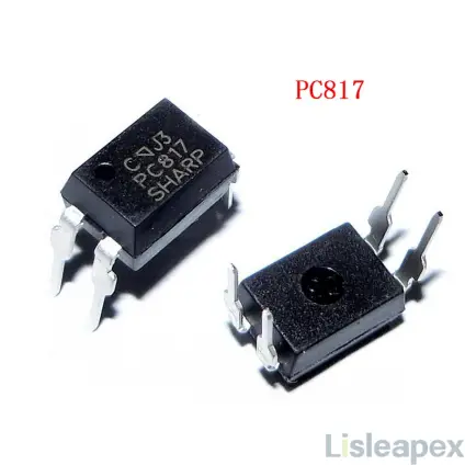
PC817 Description
The PC817 optocoupler is a fundamental component in electronic circuits, seamlessly integrating an infrared emitting diode (IR LED) and a phototransistor to establish an optical linkage between them. This optical coupling enables the transmission of electrical signals between the input and output sides without requiring any physical connection, ensuring efficient electrical isolation in diverse circuit designs.
Available in various compact packages, the PC817 offers exceptional versatility, making it suitable for integration into a wide range of electronic systems. Its compatibility with low-voltage DC devices or microcontrollers enhances its applicability across different applications, providing flexibility and ease of use.
With robust performance characteristics, the PC817 operates reliably across a wide range of operating conditions. It boasts a maximum collector-emitter voltage (VCEO) of up to 80V and an internal resistance of 100Ω, facilitating efficient current transfer and ensuring stable signal transmission. Additionally, built-in protection for both input and output enhances reliability and durability in demanding environments.
The PC817 is designed to meet specific application requirements, offering multiple grades of Current Transfer Ratio (CTR) for customization based on signal amplification needs. Its fast response times, including fall and rise times of 18μs, ensure rapid signal transmission, making it suitable for high-frequency applications. Furthermore, the optocoupler provides robust protection against electrical interference with isolation voltage of 5.0kV between input and output, ensuring safe and reliable operation in various electronic systems.
Brief of Optocouplers
Optocouplers enable you to transmit signals to circuits that are completely isolated from the electronic environment. Think of an optocoupler as a transistor, but instead of emitting electrical signals, it emits light. A phototransistor from another circuit receives the light signals and either opens or closes the circuit. From an electrical perspective, this achieves complete isolation.
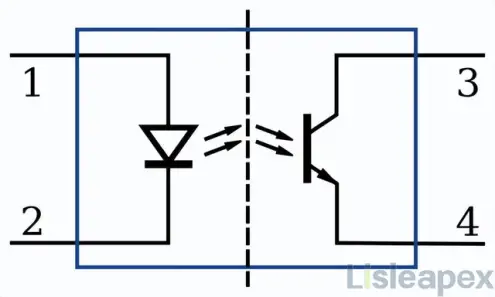
Optocoupler electronic symbol
PC817 Pinout
The PC817 optocoupler features four pins, with Pins 1 and 2 dedicated to infrared LED input, and Pins 3 and 4 serving as phototransistor output.
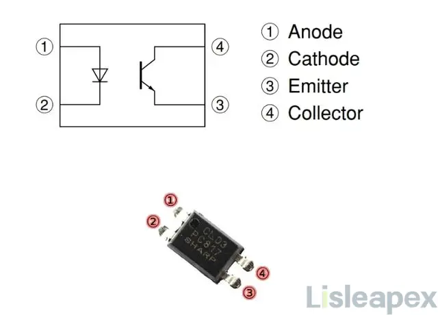
Pin details,
- Anode (+) Pin (Pin 1): Inputs logic signal to the internal infrared LED.
- Cathode (-) Pin (Pin 2): Connected to the circuit and power supply common ground.
- Emitter Pin (Pin 3): Establishes a common ground connection similar to the cathode pin, providing a ground reference.
- Collector Pin (Pin 4): Transmits logic output when receiving an infrared signal.
Pin Configuration Table:
|
Pin Number |
Function |
Description |
|
1 |
Anode (+) |
Inputs logic signal to the internal infrared LED. |
|
2 |
Cathode (-) |
Connected to the circuit and power supply common ground. |
|
3 |
Emitter |
Establishes a common ground connection similar to the cathode pin. |
|
4 |
Collector |
Transmits logic output when receiving an infrared signal. |
This pin configuration allows for effective signal transmission and isolation in various electronic applications.
PC817 Specifications and Features
Specifications
- Package Type: 4-pin DIP and SMT
- Maximum VCEO (Collector-Emitter Voltage): 80V
- Forward Voltage of Input Diode: 1.25V
- Maximum Operating Temperature Range: -30°C to 100°C
- Internal Resistance: 100Ω
- Internal Storage Temperature Range: -55°C to 125°C
- Internal Protection for Input and Output
- CTR (Current Transfer Ratio) Available in Multiple Grades
- Fall Time: 18μs
- Rise Time: 18μs
- Maximum Collector Current: 50mA
- Maximum Power Dissipation: 200mW
- Isolation Voltage Between Input and Output: 5.0kV
- Cutoff Frequency: 80kHz
Features
- Maximum Collector-Emitter Voltage (VCEO) of up to 80V.
- Internal resistance of 100Ω for efficient current transfer.
- Reliable operation within a wide temperature range of -30°C to 100°C.
- Built-in protection for both input and output.
- Offers multiple grades of Current Transfer Ratio (CTR) to suit various application requirements.
- Fast response with fall and rise times of 18μs.
- Maximum collector current of 50mA and maximum power dissipation of 200mW.
- Provides isolation voltage of 5.0kV between input and output.
- Cutoff frequency of 80kHz, suitable for high-frequency applications.
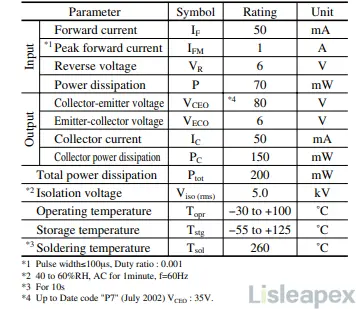
Absolute Maximum Ratings(Ta=25˚C)
Working Principle of PC817(How to Use)
The operation of the PC817 optocoupler is straightforward, yet its integration with diverse devices necessitates adherence to specific specifications. At the input, a current-limiting resistor is essential to regulate the current supplied to the optocoupler. Conversely, at the output, connecting the logic output pin to the power pin is required. When an infrared signal is generated, this induces a transition in logic state from 1 to 0, facilitated by the alteration in current flow.
For example, here is a PC817 Optocoupler Circuit,
The PC817 optocoupler is a commonly used component for electrical isolation and signal transmission applications. It consists of an infrared LED and a phototransistor, capable of providing electrical isolation between input and output. In this circuit, the conduction state of the infrared LED is controlled by the logic input, thereby influencing the conduction state of the phototransistor and achieving the conversion of logic input signals to logic output signals.
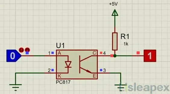
Detailed Circuit Description:
When the logic input is low, both the infrared LED and the phototransistor remain in a non-conductive state, resulting in a high logic output. In this scenario, the collector of the phototransistor is pulled up to a voltage close to the supply voltage using a 1K pull-up resistor.
When the logic input is high (greater than or equal to 1.25V), the infrared LED becomes conductive, causing the phototransistor to also conduct. This results in a short circuit between the collector and emitter of the phototransistor, pulling the logic output voltage down to zero. Therefore, changes in the logic input signal directly affect the state of the logic output signal.
The rise and fall times of the PC817 optocoupler are both specified at 18μs, indicating fast response times. The circuit structure involves connecting the anode of the infrared LED to the isolated logic input, connecting the cathode to ground, pulling the collector up to the supply voltage using a 1K resistor, connecting the collector to the output of the logic circuit, and finally connecting the emitter to ground. It is important to note that the ground connections of the infrared LED and the phototransistor are left unconnected to ensure electrical isolation between input and output.
This design enables the PC817 optocoupler to effectively transmit logic signals from one circuit to another while providing the necessary electrical isolation to prevent signal interference and equipment damage.
Note: Ensuring Long-Term Safe Usage in Circuits:
To ensure the stable and safe operation of the PC817 optocoupler in your circuit, it is recommended to operate it within its maximum rated specifications at all times. The load should not be driven beyond 50mA, unlike regular LEDs. To regulate the current to the internal infrared LED, a current-limiting resistor should be employed at pin-1 (the anode or cathode pin of the IR LED).
The component should not be operated beyond temperatures of -30°C to 100°C. It is imperative to operate and store the component within the temperature range of -55°C to 125°C.
This approach guarantees the longevity and reliability of the PC817 optocoupler in your circuit, ensuring consistent performance under varying operating conditions.
PC817 Example(Application & Uses)
The PC817 optocoupler finds widespread application in the IoT field, particularly in home automation and heavy load control scenarios. One notable application involves controlling AC loads by detecting zero-crossings in the frequency signal.
By utilizing the zero-cross method, changes in AC voltage frequency can be effectively monitored, enabling precise control over AC loads. The optocoupler plays a crucial role in generating consistent pulses to detect these frequency changes, facilitating seamless integration with microcontrollers for simplified control of high AC loads.
The PC817 optocoupler, renowned for its electrical isolation capabilities, finds widespread use in various applications aimed at reducing noise interference and ensuring signal integrity between different electrical components and circuits. Its versatility and efficiency make it an indispensable component in modern electronic systems. Below are some of its key applications:
Microcontroller I/O Isolation:
The PC817 serves as an effective interface between microcontrollers and external devices by providing electrical isolation, safeguarding the microcontroller from voltage spikes and other potential disturbances in the external circuitry.
General Electrical Isolation Purposes:
Employed for isolation in numerous electrical systems, the PC817 ensures reliable transmission of signals while mitigating risks associated with ground loops and voltage differentials.
Switching Circuits with Noise Coupling:
In switching circuits, the PC817 effectively suppresses noise coupling, ensuring clean and reliable signal switching without compromising system performance. Its isolation capability helps maintain signal integrity, particularly in environments prone to electromagnetic interference (EMI).
IoT Devices:
The PC817 plays a crucial role in Internet of Things (IoT) devices, facilitating communication between interconnected sensors, actuators, and control systems while ensuring electrical isolation to prevent interference and damage.
Signal Transmission Across Different Potentials:
Utilized for transmitting signals between circuits with varying potentials and impedances, the PC817 ensures seamless communication while isolating sensitive components from potentially harmful voltage levels.
AC Load Control in Home Appliances:
In home appliances requiring AC load control, such as dimmers and motor speed controllers, the PC817 enables precise switching and modulation of AC power, enhancing energy efficiency and operational flexibility.
Signal Transmission in Mixed-Signal Systems:
Widely deployed in mixed-signal systems, the PC817 facilitates signal transmission between digital and analog circuits while maintaining isolation to prevent noise interference and signal distortion.
Application Circuit Diagram
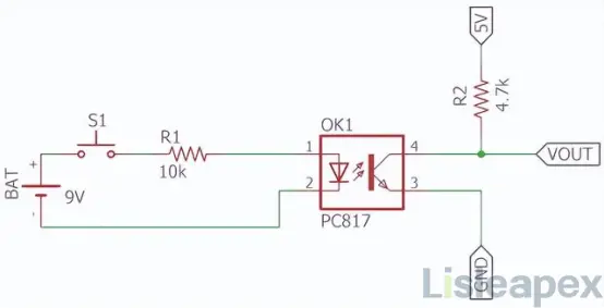
The upper circuit employs an optocoupler circuit based on a phototransistor, functioning similarly to a standard DC transistor switch. The schematic utilizes the low-cost optocoupler PC817, where switch S1 controls the infrared LED. When the switch is open, a 9V battery source provides current to the LED via a 10k current-limiting resistor (R1), with R1 regulating the intensity. Altering R1 to decrease resistance increases LED intensity, thus boosting transistor gain.
On the other hand, the transistor is a phototransistor controlled by an internal infrared LED. When the LED emits infrared light, the phototransistor conducts, causing VOUT to go low, thereby interrupting the load connected across it. It's crucial to note that, as per the datasheet, the transistor's collector current is 50mA. VOUT at 5V is provided by R2, which acts as a pull-up resistor.
PC817 Project with Arduino
(1) PC817 Optocoupler and 2N2222 Transistor with arduino
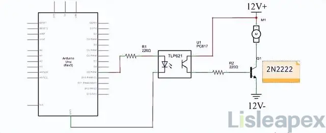
This circuit example demonstrates the interfacing of an Arduino Uno board with a PC817 optocoupler and a 2N2222 transistor.
Two 220Ω resistors are incorporated into the circuit:
The first resistor is connected between pin 9 of the Arduino board and the positive terminal of the optocoupler. This resistor serves to reduce the voltage across the circuit to prevent overdriving the LED and damaging it. Adjustments to this resistor may be necessary if using a different optocoupler model, as the maximum LED input voltage for the PC817 is 1.4V, and the resistor lowers the Arduino's 5V output to 1.25V.
The second 220Ω resistor limits the current flowing through the phototransistor in the optocoupler. While the SHARP PC817 can handle up to 50mA at 35V, operating under these conditions may lead to excessive heat and reduced longevity. Therefore, a current-limiting resistor is added to the circuit to maintain safe operation.
(2) PC817 Optocoupler Dimmer Control with Arduino
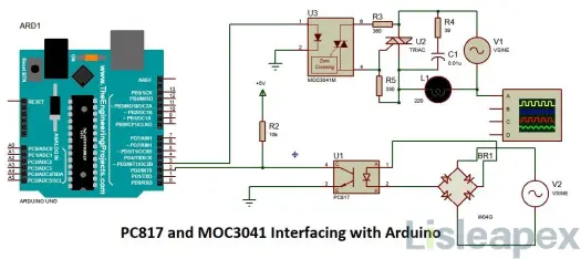
This circuit example illustrates the use of a PC817 optocoupler for controlling a dimmer with an Arduino microcontroller. The zero-crossing detection pin is connected to an interrupt pin on the Arduino, while any digital pin can be utilized to control the dimming signal. Although the pins for the infrared (IR) and dimmer are depicted in the image, they are not specific and can be configured as needed.
The Arduino sketch provided demonstrates how zero-crossing detection can be utilized in conjunction with the Arduino to control high voltages. The code enables smooth dimming of the connected load by synchronizing the switching of a triac with the AC waveform's zero-crossing points. Adjustments can be made to the code to accommodate multiple dimmers, if necessary.
Arduino sketch
Controlling High Voltages with Arduino and Zero-Cross Detection
Code Overview:
This code snippet demonstrates how to use zero-cross detection with an Arduino to control high voltages, such as for dimming applications:
- Initialization: Variables are initialized and pin configurations are set up.
- Zero-Cross Detection: An interrupt function detects zero-crossings, resetting counters and controlling the AC pin accordingly.
- Dimming Control: Another function adjusts the dimming level based on zero-crossing events, controlling the connected light.
While this code is for a single dimmer, modifications are needed to support multiple dimmers.


PC817 Alternative & Equivalents
PC817 Alternative Optocouplers include TLP521, HCNR201, MOC3021, MOC3041, 6N136, 4N25, 6N137, FOD3180, and MCT2E, while its Equivalents encompass PC816, PC123, TLP621, TLP321, TLP421, PC17K1, H11A817, SFH615A, PS2501-1, PS2561-1, PS2571-1, LTV-816, LTV-817(-V), LTV123, LTV-610, K1010, and K817P.
PC817 Test Circuit
(1)Test Circuit for Response Time
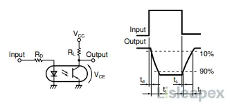
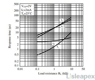
Response Time vs. Load Resistance
(2) Test Circuit for Frequency Response
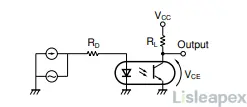
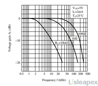
Frequency Response
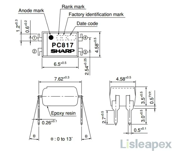
2D-Model and Dimensions
Datasheet PDF
Download PC817 datasheet PDF here>>
Conclusion
In conclusion, the PC817 optocoupler stands as a beacon of efficiency and reliability in the realm of electronic circuitry. With its seamless integration of an IR LED and phototransistor, it facilitates the transmission of signals across isolated circuits, ensuring robust electrical isolation and stable performance. From home automation to IoT devices, it finds widespread application, empowering engineers and enthusiasts alike to achieve seamless signal transmission and efficient circuit operation. As technology continues to evolve, the PC817 remains a cornerstone component, driving innovation and progress in electronic design.
訂閱時事通訊,了解 亮辰科技 的最新動態
