 恭喜您提交成功
 提交失敗
提交失敗
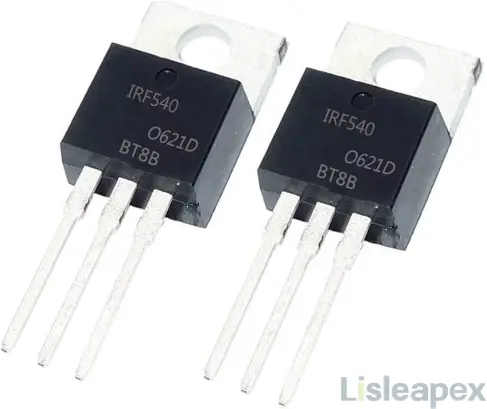
The IRF540 MOSFET, renowned for its N-channel enhancement and trench technology, stands as a versatile component in electronic design. Widely adopted in applications like high-power switching, amplification, and motor control, its efficacy in diverse scenarios is underscored by features such as low thermal resistance and a maximum power dissipation of 100W.
Introduction to IRF540
The IRF540 stands as a widely utilized N-channel enhancement MOSFET renowned for its trench technology, rendering it proficient in various applications. Boasting low thermal resistance and cost-effectiveness in the TO-220AB package, this MOSFET has earned favor in both hobbyist and industrial electronic design circles.
Primarily designed for driving high-current loads, the IRF540 demonstrates a remarkable capacity to handle up to 23A with a maximum load voltage of 100V DC. Its trench technology not only contributes to low thermal resistance but also empowers high-level driving capabilities, enabling swift voltage switching. This versatility makes it a reliable choice for applications requiring rapid load switching, such as in Uninterruptible Power Supplies (UPS).
Beyond its prowess in switching applications, the IRF540 finds utility as an amplifier, thanks to its maximum power dissipation of 100W. This attribute positions it favorably for constructing high-power audio amplifiers and utilization in high-power audio amplifier stages.
Operating in the temperature range of -55 degrees Celsius to 175 degrees Celsius, the IRF540, based on HEXFET technology, excels in various real-life applications. Its role spans from high-power switching drivers, switching regulators, relay drivers, to switching converters and motor drivers. The TO-220 package, chosen for commercial and industrial applications, underscores the MOSFET's widespread acceptance due to its economical packaging and reduced thermal resistance.
In the realm of MOSFETs, the IRF540N represents an advanced HEXFET power MOSFET manufactured by International Rectifier. Leveraging intricate processing methods, it achieves low on-resistance per 'Si' area, delivering rapid switching speed and robust device design. Encased in the TO-220 package, its cost-effectiveness and diminished thermal resistance contribute to broad industry acceptance.
With its three terminals - source, drain, and gate - the IRF540N showcases flexibility in voltage and current switching capacities, making it an ideal choice for diverse electronic applications. Its working principle involves applying a signal to the Gate terminal, resulting in shorting between the Drain and Gate terminals, ensuring precise and efficient outcomes in electronic circuits.
How Does IRF540 Work
The operational principle of the IRF540 is uncomplicated. One terminal serves as the N-type transistor entrance, whereas the remaining two terminals are also N-type. When a current is applied to the gate terminal, it triggers a shorting between the gate and the drain.
Furthermore, the drain and the source function as the electron collector and emitter, respectively. Additionally, the wiring configuration of MOSFETs closely resembles that of Bipolar Junction Transistors (BJTs). The primary distinction lies in the control mechanism: MOSFETs are voltage-controlled, whereas BJTs are current-controlled.
Where to Use IRF540N
The IRF540N, an N-Channel MOSFET, finds application in scenarios demanding robust load-driving capabilities, accommodating loads of up to 23A and sustaining peak currents reaching 110A. With a threshold voltage of 4V, it proves compatible with low-voltage signals, such as those from microcontrollers like Arduino. This MOSFET is particularly favored for logic switching in conjunction with microcontrollers.
Its versatile utility extends to applications involving speed control of motors and light dimmers, leveraging its commendable switching characteristics. Consequently, the IRF540N emerges as an optimal choice for situations where the need arises to switch high-current applications in conjunction with logic-level devices.
How to Use IRF540N
To effectively utilize the IRF540N, it is crucial to understand that MOSFETs operate as voltage-controlled devices, differing from transistors. The state of the MOSFET, whether turned on or off, is determined by applying the requisite Gate threshold voltage (VGS). In the case of the IRF540N, an N-channel MOSFET, the Drain and Source pins remain open when no voltage is applied to the Gate pin. Closing the connection between Drain and Source occurs when a gate voltage is applied.
The schematic below illustrates the behavior of the IRF540N when the Gate voltage is either applied (5V) or not applied (0V). As an N-channel MOSFET, the load to be switched, such as a motor, should always be connected above the Drain pin.
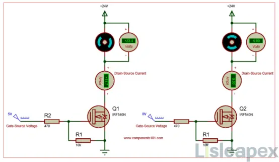
When turning on a MOSFET by supplying the necessary voltage to the Gate pin, it will stay on until a 0V signal is applied to the Gate. To prevent this issue, the inclusion of a pull-down resistor (R1) is essential. In practical applications involving tasks like motor speed control or light dimming with PWM signals for rapid switching, the MOSFET's gate capacitance can induce reverse current due to parasitic effects. To mitigate this, the utilization of a current-limiting capacitor is recommended; in this example, a capacitor with a value of 470 is employed.
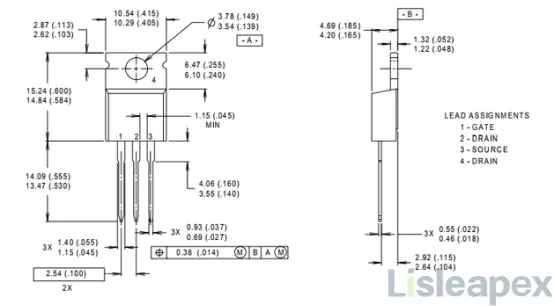
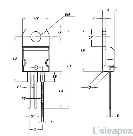
2D Model and Dimensions
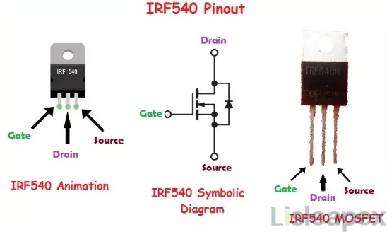
IRF540 Pinout
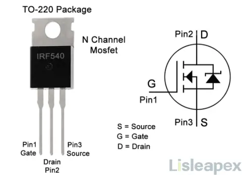
Pin Configuration
|
Pin |
Function |
Description |
|
1 |
Gate |
Facilitates MOSFET biasing control. |
|
2 |
Drain |
Current enters the MOSFET through this pin. |
|
3 |
Source |
Current exits the MOSFET through this pin. |
Pin Diagram
IRF540 Specifications
- Type: N-Channel Enhancement Mode MOSFET
- Mounting: Through Hole
- Package/Case: TO-220-3
- Transistor Element Material: Silicon
- Operating Temperature: -55°C to 175°C
- Packaging: Tube
- Series: STripFET™ II
- Part Status: Obsolete
- Moisture Sensitivity Level (MSL): 1 (Unlimited)
- Number of Terminations: 3
- ECCN Code: EAR99
- Terminal Finish: Matte Tin (Sn)
- Voltage - Rated DC: 100V
- Current Rating: 22A
- Power Dissipation-Max: 85W at Tc
- Rds On (Max) @ Id, Vgs: 77mΩ @ 11A, 10V
- Vgs(th) (Max) @ Id: 4V @ 250μA
- Input Capacitance (Ciss) (Max) @ Vds: 870pF @ 25V
- Continuous Drain Current (ID) @ 25°C: 22A at Tc
- Gate Charge (Qg) (Max) @ Vgs: 41nC @ 10V
- Rise Time: 45ns
- Drive Voltage (Max Rds On, Min Rds On): 10V
- Vgs (Max): ±20V
- Fall Time (Typ): 20ns
- Turn-Off Delay Time: 50ns
- JEDEC-95 Code: TO-220AB
- Gate to Source Voltage (Vgs): 20V
- Drain-Source On Resistance-Max: 0.077Ω
- Drain to Source Breakdown Voltage: 100V
- Avalanche Energy Rating (Eas): 220mJ
- Turn Off Time-Max (toff): 230ns
- RoHS Status: Non-RoHS Compliant
- Lead-Free: Contains Lead
IRF540 Ratings
The table below presents the current, voltage, and power ratings of the IRF540, accompanied by their respective values in the System International (SI) units.
|
Parameter |
Rating |
SI Units |
|
Continuous Drain Current |
23A |
Amperes (A) |
|
Pulsed Drain Current |
110A |
Amperes (A) |
|
Gate Threshold Voltage (VGS-th) |
2V - 4V |
Volts (V) |
|
Gate-Source Voltage (VGS) |
±20V |
Volts (V) |
|
Maximum Drain-Source Voltage (VDS) |
100V |
Volts (V) |
|
Power Dissipation |
100W |
Watts (W) |
|
Turn ON Time |
35ns |
Nanoseconds (ns) |
These specifications provide a comprehensive overview of the IRF540's electrical characteristics, crucial for informed and accurate utilization in electronic circuits.
IRF540 Features
- N-channel enhancement MOSFET
- Trench technology for improved performance
- Low thermal resistance
- TO-220AB package for cost-effectiveness
- Designed for high-current load driving
- Maximum continuous drain current: 23A
- Maximum load voltage: 100V DC
- Suitable for high-speed switching applications
- Versatile usage in switching and amplification
- Maximum power dissipation: 100W
- Wide temperature range: -55 to +175 degrees Celsius
- Popular for applications like UPS, motor speed control, and amplifiers.
Advantages of IRF540
- Efficient Current Flow with Low On-Resistance (RDS(on) = 0.055Ω)
- High Capability for Handling Rapid Voltage Changes (dv/dt)
- Rigorous Avalanche Testing Ensures Robustness
- Swift and Energy-Efficient Switching with Low Gate Charge
- Tailored Design Considerations for Application-specific Performance
- Simple Drive Signal Requirements
- Easy Parallel Connection for Scalability
- Fast Switching, Ideal for Dynamic Applications
IRF540 Application
- Power Electronics: Used in switching high-power devices for efficient power management.
- Motor Control: Ideal for controlling the speed of motors in various applications.
- Lighting Systems: Employed in LED dimmers and flashers for adjustable illumination.
- High-Speed Switching: Suitable for applications requiring rapid switching, ensuring quick response times.
- Power Conversion: Integral in converters and inverter circuits for transforming electrical energy.
- Uninterruptible Power Supplies (UPS): Ensures a continuous power supply during electrical disruptions.
- Battery Charging: Utilized in battery chargers for effective charging processes.
- Battery Management Systems: Plays a role in managing and optimizing battery performance.
- Solar Energy Applications: Used in solar battery chargers and solar uninterruptible power supplies.
- Motor Drive Systems: Applied in motor driver circuits for precise control of electric motors.
- Telecommunications: Contributes to the efficient operation of electronic communication systems.
- Computer-related Applications: Used in various electronic components for reliable performance.
- High-Efficiency DC-DC Converters: Employed in circuits designed for efficient direct current (DC) conversion.
- Amplification: Capable of amplifying signals, making it suitable for audio and signal processing applications.
The IRF540's diverse applications showcase its adaptability across different electronic systems, making it a popular choice for engineers and hobbyists in various fields.
Application Circuit of IRF540
The IRF540, a widely used N-channel MOSFET, finds versatile applications in electronic circuits. Here, we explore its application in motor control, buck converter, PWM motor switching, and power inverter circuits, highlighting the key components and functionalities in each setup.
1. Motor Control Circuit:
In this application, the IRF540 serves as the central component for controlling a DC motor. The circuit incorporates a microcontroller or a simple switch to drive the MOSFET, enabling precise motor speed regulation.
Key Components:
- IRF540 N-channel MOSFET
- DC Motor
- Microcontroller or Switch for Control
- Diode for Freewheeling (e.g., 1N4148)
2. Buck Converter:
The IRF540 is employed in a buck converter circuit to step down voltage efficiently. This application is suitable for various power supply designs, ensuring a stable output voltage with reduced input voltage.
Key Components:
- IRF540 N-channel MOSFET
- Inductor
- Capacitor
- Diode
- Control Circuit (e.g., PWM controller)
3. PWM Motor Switching:
This circuit utilizes the IRF540 for Pulse Width Modulation (PWM) motor control. The MOSFET switches the motor on and off rapidly, controlling the effective power delivered to the motor and thereby regulating its speed.
Key Components:
- IRF540 N-channel MOSFET
- DC Motor
- PWM Controller or Microcontroller
- Diode for Freewheeling
4. Power Inverter:
In a power inverter application, the IRF540 facilitates the conversion of DC power to AC power. It is a crucial component for switching the DC input and generating alternating current for various applications, such as powering household appliances.
Key Component
- IRF540 N-channel MOSFETs (Multiple for H-bridge configuration)
- DC Input Source (e.g., Battery)
- Inductor
- Capacitors
- Control Circuit (e.g., Microcontroller)
5. Zero Drop Solar Switch:
This application involves using the IRF540 in a solar power switching circuit to minimize voltage drops. The MOSFET efficiently switches the solar power source, ensuring maximum power transfer and minimizing energy losses.
Key Components:
- IRF540 N-channel MOSFET
- Solar Panels
- Control Circuit (e.g., Microcontroller)
- Diode for Reverse Current Protection
IRF540 Test Circuits
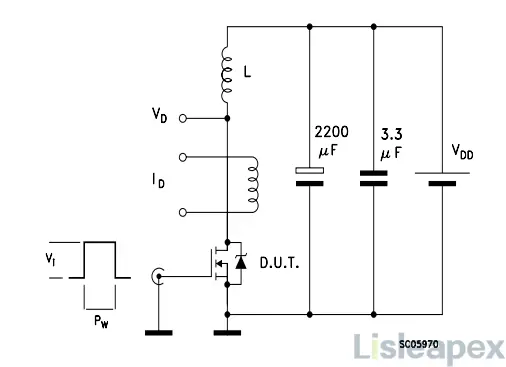
Unclamped Inductive Load Test Circuit
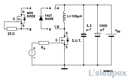
Inductive Load Switching And Diode Recovery Times
IRF540 Proteus ISIS Simulation
The IRF540 Proteus simulation for DC motor control serves as an efficient method to understand and implement motor control using the IRF540 MOSFET and an Arduino UNO. This simulation includes two scenarios, one involving a simple switch control and the other integrating an Arduino UNO for more advanced control.
Simulation 1: Simple Switch Control
In this scenario, a basic setup is created using an IRF540 MOSFET for DC motor control. The switch is utilized to trigger the motor, and the simulation depicts the motor starting upon closing the switch. The visual representation includes a color change of the motor to blue during operation.
Simulation 2: Arduino UNO Integration
The second simulation involves interfacing an Arduino UNO with the IRF540 for enhanced control. A signal is sent from the Arduino to an optocoupler, and the output of the optocoupler is connected to the IRF540. Additionally, a diode (1N4148) is incorporated for security reasons, preventing current flow in the reverse direction.
Arduino Code:
int MotorInput = 2;
int MotorOutput = 7;
void setup()
{
pinMode(MotorInput, INPUT_PULLUP);
pinMode(MotorOutput , OUTPUT);
}
void loop()
{
if(digitalRead(MotorInput) == HIGH)
{
digitalWrite(MotorOutput, HIGH);
}
if(digitalRead(MotorInput) == LOW)
{
digitalWrite(MotorOutput, LOW);
}
}
This Arduino code enables motor control based on the input state, and the corresponding Proteus simulation demonstrates the motor's rotation upon changing the logic state.
Verification and Testing:
To validate the functionality, upload the provided Arduino code and obtain the .hex file. Run the Proteus simulation with the uploaded .hex file. Changing the logic state from 0 to 1 activates the green LED, indicating proper circuit functionality, and the motor starts rotating in either direction.
The IRF540 Proteus simulation for DC motor control provides a comprehensive understanding of MOSFET-based motor control, catering to both basic and Arduino-integrated scenarios. This simulation serves as a valuable tool for learning and implementing motor control systems using the IRF540 MOSFET and Arduino UNO.
How to Safely Long Run in a Circuit
To ensure the sustained and safe long-term operation of the circuit, it is advisable to operate the components at least 20% below their specified maximum ratings. Considering the IRF540N MOSFET, with a maximum drain current of 23A, it is recommended to operate it below 18A. Similarly, the maximum load voltage is specified at 100V, and it is prudent to maintain the load under 80V for extended reliability. Additionally, the Gate-to-Source voltage should be kept within the range of ±20V.
Incorporating a suitable heatsink is imperative to manage thermal dissipation effectively. This measure aids in preventing the MOSFET from reaching elevated temperatures that could compromise its performance or longevity.
Furthermore, the operating and storage temperatures should be carefully observed. The MOSFET is designed to function within a temperature range of -55 to +155 degrees Celsius. Operating within these specified temperature limits is essential to ensure optimal performance and longevity over an extended period.
IRF540 Replacement & Equivalent
Substitute and Equivalent MOSFETs for IRF540:
2SK1928
BUZ21
2SK2314
2SK2466
2SK2391
BUK445-100A
BUK455-100A
BUK551-100A
BUK555-100A
IRFI540G
IRFS540
MTP27N10E
RFP22N10
2SK2789
IRF540 Alternative Options:
IRF034
IRF044
IRF044SMD
IRF054
IRF054SMD
IRF100B201
IRF540 vs IRF540N: What are Differences
|
Feature |
IRF540 |
IRF540N |
|
Description |
N-channel power MOSFET in TO-220AB package |
N-channel power MOSFET in TO-220AB package |
|
Processing Technology |
Advanced techniques for low on-resistance |
Cutting-edge process technology |
|
Switching Speed |
Fast switching speed, ruggedized design |
Fast switching capabilities |
|
Package Type |
TO-220AB preferred for commercial-industrial applications |
TO-220AB preferred for commercial-industrial applications |
|
Voltage Ratings |
Max Drain to Source Voltage - 100V |
Max Drain to Source Voltage - 100V, Max Gate to Source Voltage - ±20V |
|
Current Ratings |
Max Continuous Drain Current - 45A |
Max Continuous Drain Current - 45A (manufacturer-specific) |
|
Power Dissipation |
Max Power Dissipation - 127W |
Max Power Dissipation - 120W (manufacturer-specific) |
|
On-Resistance |
Typical Drain to Source On Resistance - 0.032Ω |
Max Drain to Source On Resistance - 0.065Ω (manufacturer-specific) |
|
Temperature Range |
Operating temperature: -55 to +175 Celsius |
Operating temperature: -55 to +175 Celsius |
|
Advantages |
Fast switching, rugged design |
Cutting-edge technology, ultra-low on-resistance, fully avalanche rated, capable of wave-soldering |
In summary, both the IRF540 and IRF540N are N-channel power MOSFETs encapsulated in the TO-220AB package, suitable for commercial and industrial applications. The IRF540N distinguishes itself with cutting-edge process technology, offering ultra-low on-resistance, full avalanche rating, and the capability of being wave-soldered. Its advantages include enhanced performance and robustness. On the other hand, the IRF540 features advanced techniques for achieving low on-resistance per silicon area, ensuring fast switching speed and a ruggedized design. While both models share similarities in their voltage ratings, current capacities, and operational temperature range, the IRF540N stands out for its technological advancements and specific capabilities, making it a preferred choice for applications demanding superior efficiency and reliability.
IRF540 vs IRFZ44 vs BUZ21: What are Differences
In this comparison table, we analyze the electrical specifications of three MOSFET devices - IRF540, IRFZ44, and BUZ21, with the aim of facilitating the replacement process.
|
Characteristics |
IRF540 |
IRFZ44 |
BUZ21 |
|
Drain to Source Voltage (VDS) |
100V |
60V |
100V |
|
Gate to Source Voltage (Vgs) |
20V |
20V |
20V |
|
Gate Threshold Voltage (Vg(th)) |
2 to 4V |
2 to 4V |
3 to 4V |
|
Drain Current (Id) |
20A to 28A |
36A to 50A |
19A |
|
Total Gate Charge (Qg) |
72nC |
67nC |
- |
|
Power Dissipation (PD) |
200W |
150W |
75W |
|
Junction Temperature (TJ) |
-55 to +175°C |
-55 to +175°C |
-55 to +175°C |
|
Drain to Source On-State Resistance (RDS) |
0.007Ω |
0.028Ω |
0.09 to 0.1Ω |
|
Rise Time (tr) |
44ns |
110ns |
50 to 75ns |
|
Reverse Recovery Time (trr) |
180 to 360ns |
120 to 180ns |
200ns |
|
Package |
TO-220AB |
TO-220AB |
TO-220AB |
The electrical specification comparison reveals remarkable similarities among IRF540, IRFZ44, and BUZ21. With nearly identical specifications in voltage ratings, current capacities, and thermal characteristics, these MOSFETs can effectively serve as replacements for one another in diverse applications. This alignment in specifications provides valuable flexibility for engineers and designers during the replacement process.
Package Outline
Manufacturer
Vishay Intertechnology, Inc. is a global manufacturer of electronic components. The company produces a wide range of products, including resistors, capacitors, inductors, sensors, optoelectronics, and integrated circuits. Vishay's components are used in various applications across industries such as automotive, industrial, telecommunications, computing, and consumer electronics.
The company was founded in 1962 by Dr. Felix Zandman in the United States and has since grown into a prominent player in the electronic components industry. Vishay is known for its commitment to quality and innovation in electronic components, and it serves a diverse customer base worldwide.
Datasheet
Download IRF540 datasheet here>>
Conclusion
In essence, the IRF540 MOSFET offers efficient current flow, swift switching capabilities, and a broad operating temperature range, making it an ideal choice for applications ranging from power electronics and motor control to lighting systems and high-speed switching. Its specifications, features, and applications collectively portray the IRF540 as a reliable and adaptable component in the realm of electronic systems.
訂閱時事通訊,了解 亮辰科技 的最新動態
