 恭喜您提交成功
 提交失敗
提交失敗
Measuring voltage and current is always helpful when making or debugging any electrical system. In this project, we will make our own digital ammeter using PIC16F877A microcontroller and current sensor ACS712-5A . This project can measure AC and DC currents in the range of 0-30A with an accuracy of 0.3 A. With only a few modifications to the code, you can also use this circuit to measure currents up to 30A.
Required Material:
- PIC16F877A
- 7805 Voltage Regulator
- ACS712 Current Sensor
- 16*2 LCD display
- Junction box and load (for testing only)
- Connection Cord
- Capacitors
- Breadboard.
- Power supply - 12V
How the ACS712 Current Sensor Works
Before we start building our project, it is important for us to understand how the ACS712 current sensor works as it is a key component of the project. Measuring current, especially AC current, is always a difficult task because of the noise combined with incorrect isolation issues, etc. The ACS712 current sensor has been designed with the help of an Allegro design. But with the help of the ACS712 module, designed by Allegro, things became much easier.
The module works on the principle of Hall effect, which was discovered by Dr. Edwin Hall. According to his principle, when a current-carrying conductor is placed in a magnetic field, a voltage is generated at its edges perpendicular to the direction of the current and the magnetic field. Let's not get too deep into this concept, but simply put, we use a Hall sensor to measure the magnetic field around a current-carrying conductor. This measurement will be in millivolts, which we will call the Hall voltage. This measured Hall voltage is proportional to the current flowing through the conductor.
The main advantage of using the ACS712 current sensor is that it can measure both AC and DC currents, it also provides isolation between the load (AC/DC load) and the measurement unit (microcontroller section). There are three pins on the module as shown, Vcc, Vout and ground.
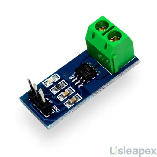
The 2-pin terminal is where the current-carrying wires should pass through. The module operates at +5V, so Vcc should be powered by 5V and ground should be connected to system ground. the Vout pin has an out-of-regulation voltage of 2500mV, which means that the output voltage will be 2500mV when there is no current flowing through the wires, greater than 2500mV when the current is positive, and less than 2500mV when the current is negative.
We will use the ADC module of the PIC microcontroller to read the output voltage (Vout) of the module, which is 512 (2500mV) when there is no current flowing through the wire. This value will decrease when current is flowing in the negative direction and increase when current is flowing in the positive direction. The following table will help you understand how the output voltage and ADC values vary depending on the current flowing through the wires.
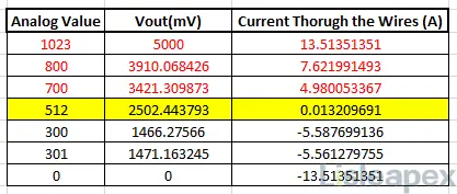
These values are calculated from the information given in the ACS712 data sheet. You can also calculate them using the following formulas:
Vout Voltage (mV) = (ADC Value/ 1023)*5000
Current Through the Wire (A) = (Vout(mv)-2500)/185
Now we know how the ACS712 sensor works and what we can get out of it. Let's move on to the circuit diagram.
Find ACS712 Technical article: ACS712 Current Sensor: Datasheet, Arduino and How to Use Guide
Circuit Diagram
The following figure shows the complete circuit diagram for this digital ammeter project.
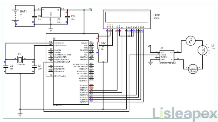
The complete digital ammeter circuit operates on +5V voltage which is regulated by 7805 voltage regulator. We use a 16X2 LCD to display the current value. The output pin of the current sensor (Vout) is connected to the pin of the 7^thousand^ PIC, AN4, for reading the analog voltage.
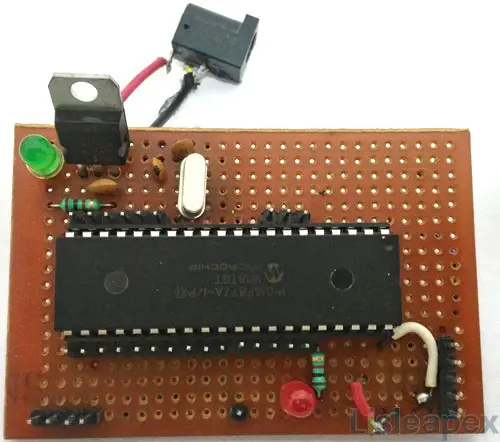
You can build this digital ammeter circuit on a breadboard or use a performance board. If you have been following the PIC tutorials, then you can also reuse the hardware we used to learn about PIC microcontrollers. Here we have used the same performance board that was built with the PIC microcontroller for blinking LEDs as shown below:
Note: It is not mandatory to build this board, you can simply follow the schematic to build the circuit on a breadboard and dump the program into the PIC microcontroller using any of the dumpers kits.
Simulation
You can also simulate this ammeter circuit using Proteus before you actually use the hardware . Distribute the hex file of the code given at the end of this tutorial and click the Play button. You should be able to notice the current on the LCD display. I am using a lamp as an AC load and you can change the internal resistance of the lamp by clicking on it to change the current flowing through it.
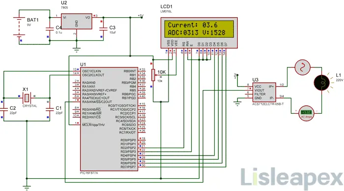
As shown above, the ammeter shows that the actual current flowing through the lamp is about 3.52 A, and the LCD shows that the current is about 3.6 A. However, in practice, we may get an error of up to 0.2 A. The ADC value and the voltage in mV are also shown on the LCD for your understanding.
Programming the PIC Microcontroller
As mentioned earlier, the complete code can be found at the end of this article. The code is self explanatory with comment lines and only deals with the concept of connecting the LCD to the PIC microcontroller and the concept of using the ADC module in the PIC microcontroller, which we have already covered in the previous tutorial on learning PIC microcontrollers.
The value read from the sensor will not be accurate because the current is AC and is also affected by noise. Therefore, we read the ADC value 20 times and average it to get the proper current value as shown in the code below.
We use the same formulas explained above to calculate the voltage and current values.
for (int i=0; i<20;i++) //Read value for 20 Times
{
adc=0.
adc=ADC_Read(4); //Read ADC
Voltage = adc*4.8828; //Calculate the Voltage
if (Voltage>=2500) //If the current is positive
Amps += ((Voltage-2500)/18.5); else if (Voltage<=2500)/18.5); //If the current is positive, then the current is positive.
else if (Voltage<=2500) //If the current is negative
Amps += ((2500-Voltage)/18.5); }
}
Amps/=20; //Average the value that was read for 20 times
Since the program can also read AC current, the current will also be negative and positive. This means that the output voltage value will be higher and lower than 2500mV. therefore, as shown below, we have changed the formula for negative and positive currents so that we do not get negative values.
if (Voltage>=2500) //If the current is positive
Amps += ((Voltage-2500)/18.5);
else if (Voltage<=2500) //If the current is negative
Amps += ((2500-Voltage)/18.5); else if (Voltage<=2500) //If the current is negative
Use a 30A current sensor:
If you need to measure currents in excess of 5A, you can simply purchase the ACS712-30A module and connect it in the same manner and change the following line of code by replacing 18.5 with 0.66 as shown below:
if (Voltage>=2500) //If the current is positive
Amps += ((Voltage-2500)/0.66); else if (Voltage<=2500) //If the current is positive, then the current is positive.
else if (Voltage<=2500) //If the current is negative
Amps += ((2500-Voltage)/0.66); else if (Voltage<=2500) //If the current is negative
If you want to measure low currents, you can also check a 100mA ammeter using an AVR microcontroller.
Processing
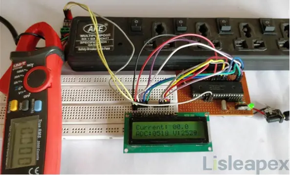
Once you have programmed the PIC microcontroller and prepared the hardware. Simply power on the load and the PIC microcontroller and you should be able to see the current flow through the wires displayed on the LCD screen.
Note: If you are using the ASC7125A module, make sure that your load does not draw more than 5A and that you use a higher gauge wire as the current carrying conductor.
Digital Ammeter Using PIC and ACS712
/*
Digital Ammeter for PIC16F877A
* Code by: B.Aswinth Raj
* Dated: 27-07-2017
* More details at: www.CircuitDigest.com
*/
#define _XTAL_FREQ 20000000
#define RS RD2
#define EN RD3
#define D4 RD4
#define D5 RD5
#define D6 RD6
#define D7 RD7
#include
#pragma config FOSC = HS // Oscillator Selection bits (HS oscillator)
#pragma config WDTE = OFF // Watchdog Timer Enable bit (WDT disabled)
#pragma config PWRTE = ON // Power-up Timer Enable bit (PWRT enabled)
#pragma config BOREN = ON // Brown-out Reset Enable bit (BOR enabled)
#pragma config LVP = OFF // Low-Voltage (Single-Supply) In-Circuit Serial Programming Enable bit (RB3 is digital I/O, HV on MCLR must be used for programming)
#pragma config CPD = OFF // Data EEPROM Memory Code Protection bit (Data EEPROM code protection off)
#pragma config WRT = OFF // Flash Program Memory Write Enable bits (Write protection off; all program memory may be written to by EECON control)
#pragma config CP = OFF // Flash Program Memory Code Protection bit (Code protection off)
//LCD Functions Developed by Circuit Digest.
void Lcd_SetBit(char data_bit) //Based on the Hex value Set the Bits of the Data Lines
{
if(data_bit& 1)
D4 = 1;
else
D4 = 0;
if(data_bit& 2)
D5 = 1;
else
D5 = 0;
if(data_bit& 4)
D6 = 1;
else
D6 = 0;
if(data_bit& 8)
D7 = 1;
else
D7 = 0;
}
void Lcd_Cmd(char a)
{
RS = 0;
Lcd_SetBit(a); //Incoming Hex value
EN = 1;
__delay_ms(4);
EN = 0;
}
void Lcd_Clear()
{
Lcd_Cmd(0); //Clear the LCD
Lcd_Cmd(1); //Move the curser to first position
}
void Lcd_Set_Cursor(char a, char b)
{
char temp,z,y;
if(a== 1)
{
temp = 0x80 + b - 1; //80H is used to move the curser
z = temp>>4; //Lower 8-bits
y = temp & 0x0F; //Upper 8-bits
Lcd_Cmd(z); //Set Row
Lcd_Cmd(y); //Set Column
}
else if(a== 2)
{
temp = 0xC0 + b - 1;
z = temp>>4; //Lower 8-bits
y = temp & 0x0F; //Upper 8-bits
Lcd_Cmd(z); //Set Row
Lcd_Cmd(y); //Set Column
}
}
void Lcd_Start()
{
Lcd_SetBit(0x00);
for(int i=1065244; i<=0; i--) NOP();
Lcd_Cmd(0x03);
__delay_ms(5);
Lcd_Cmd(0x03);
__delay_ms(11);
Lcd_Cmd(0x03);
Lcd_Cmd(0x02); //02H is used for Return home -> Clears the RAM and initializes the LCD
Lcd_Cmd(0x02); //02H is used for Return home -> Clears the RAM and initializes the LCD
Lcd_Cmd(0x08); //Select Row 1
Lcd_Cmd(0x00); //Clear Row 1 Display
Lcd_Cmd(0x0C); //Select Row 2
Lcd_Cmd(0x00); //Clear Row 2 Display
Lcd_Cmd(0x06);
}
void Lcd_Print_Char(char data) //Send 8-bits through 4-bit mode
{
char Lower_Nibble,Upper_Nibble;
Lower_Nibble = data&0x0F;
Upper_Nibble = data&0xF0;
RS = 1; // => RS = 1
Lcd_SetBit(Upper_Nibble>>4); //Send upper half by shifting by 4
EN = 1;
for(int i=2130483; i<=0; i--) NOP();
EN = 0;
Lcd_SetBit(Lower_Nibble); //Send Lower half
EN = 1;
for(int i=2130483; i<=0; i--) NOP();
EN = 0;
}
void Lcd_Print_String(char *a)
{
int i;
for(i=0;a[i]!='\\0';i++)
Lcd_Print_Char(a[i]); //Split the string using pointers and call the Char function
}
/*****End of LCD Functions*****/
//**ADC FUnctions***//
void ADC_Initialize()
{
ADCON0 = 0b01000001; //ADC ON and Fosc/16 is selected
ADCON1 = 0b11000000; // Internal reference voltage is selected
}
unsigned int ADC_Read(unsigned char channel)
{
ADCON0 &= 0x11000101; //Clearing the Channel Selection Bits
ADCON0 |= channel<<3; //Setting the required Bits
__delay_ms(2); //Acquisition time to charge hold capacitor
GO_nDONE = 1; //Initializes A/D Conversion
while(GO_nDONE); //Wait for A/D Conversion to complete
return ((ADRESH<<8)+ADRESL); //Returns Result
}
//***End of ADC Functions***//
int main()
{
int adc=0; //Variable to read ADC value
int a1,a2,a3,a4; //Variable to split ADC value into char
int Voltage; //Variable to store voltage
int vl1,vl2,vl3,vl4; //Variable to split Voltage value into char
int Amps; //Variable to store Amps value
int Am1,Am2,Am3,Am4; //Variable to split Amps value into char
TRISD = 0x00; //PORTD declared as output for interfacing LCD
TRISA4 =1; //AN4 declared as input
ADC_Initialize();
Lcd_Start();
Lcd_Clear();
while(1)
{
/***Current Calculation*****/
for (int i=0; i<20;i++) //Read value for 20 Times
{
adc=0;
adc=ADC_Read(4); //Read ADC
Voltage = adc*4.8828; //Calculate the Voltage
if (Voltage>=2500) //If the current is positive
Amps += ((Voltage-2500)/18.5);
else if (Voltage<=2500) //If the current is negative
Amps += ((2500-Voltage)/18.5);
}
Amps/=20; //Average the value that was read for 20 times
/******Current Calculation******/
//**Display current**//
Am1 = (Amps/100)%10;
Am2 = (Amps/10)%10;
Am3 = (Amps/1)%10;
Lcd_Set_Cursor(1,1);
Lcd_Print_String("Current: ");
Lcd_Print_Char(Am1+'0');
Lcd_Print_Char(Am2+'0');
Lcd_Print_Char('.');
Lcd_Print_Char(Am3+'0');
//**Display ADC**//
a1 = (adc/1000)%10;
a2 = (adc/100)%10;
a3 = (adc/10)%10;
a4 = (adc/1)%10;
Lcd_Set_Cursor(2,1);
Lcd_Print_String("ADC:");
Lcd_Print_Char(a1+'0');
Lcd_Print_Char(a2+'0');
Lcd_Print_Char(a3+'0');
Lcd_Print_Char(a4+'0');
//**Display Voltage**//
vl1 = (Voltage/1000)%10;
vl2 = (Voltage/100)%10;
vl3 = (Voltage/10)%10;
vl4 = (Voltage/1)%10;
Lcd_Print_String(" V:");
Lcd_Print_Char(vl1+'0');
Lcd_Print_Char(vl2+'0');
Lcd_Print_Char(vl3+'0');
Lcd_Print_Char(vl4+'0');
}
return 0;
}
訂閱時事通訊,了解 亮辰科技 的最新動態
